Origami Continuum Robot
Summary
Continuum robot arms, with their hyper-redundant continuously deformable bodies, show great promise in applications deemed impossible for traditional rigid robot arms with discrete links and joints, such as navigating tight corners without getting stuck. However, existing continuum robots suffer from excessive twisting when subjected to offset loading, even resulting from their own body weight, which reduces their dexterity and precision.
In my dissertation work, I proposed a continuum manipulator that is capable of providing passive torsional stiffness through an origami-inspired modular design, remedying the non-controllable twist typically present in continuum robots. The research work encompassed sensing, planning, and actuation aspects of the robot.
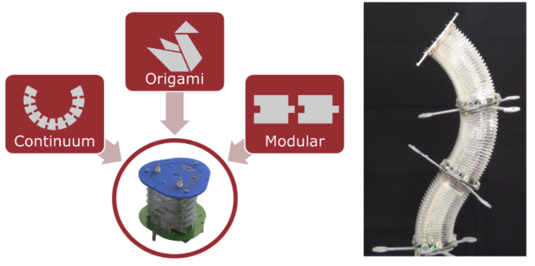 Image source: Santoso, J. (2019) Toward Deployable Origami Continuum Robot: Sensing, Planning, and Actuation. PhD Thesis, Worcester Polytechnic Institute. Available from: https://digital.wpi.edu/concern/etds/dz010s164?locale=en
Robot Design
The collapsible and compliant origami structure is made out of Polyethylene terephthalate (PET) films. The crease pattern used for this structure was designed in Solidworks and machined using a laser-cutter. The collapsible body was manually folded into 3-D following the crease pattern and later joined into an approximate triangular tube.
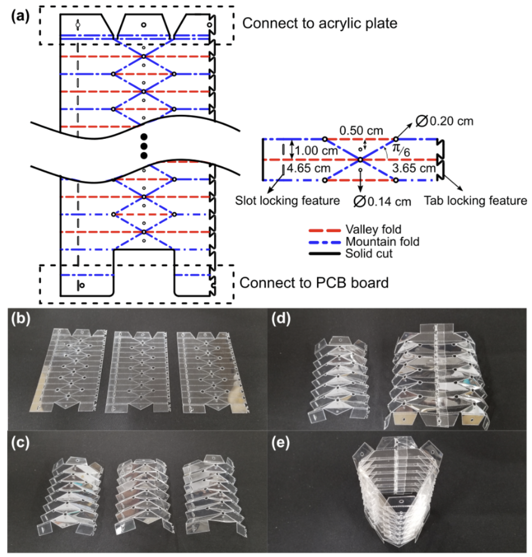
(a) Yoshimura crease pattern of the origami module with annotated dimension. (b) Perforated pattern on PET sheet engraved with laser cutter. The speed and power settings for the laser cutter are 100% and 6% respectively. The perforated pattern allows for ease of folding. (c) Folded origami sections required to construct the origami compliant body. (d) Two folded sections combined using the slot‐tab locking feature.(e) Finished compliant origami body constructed from three folded sections.1
A custom printed circuit board (PCB) was designed to achieve the actuator control and sensor reading. An AVR 8-bit microcontroller on each PCB was programmed and used to achieve the same. Multiple origami modules are connected in series to create a robotic manipulator.
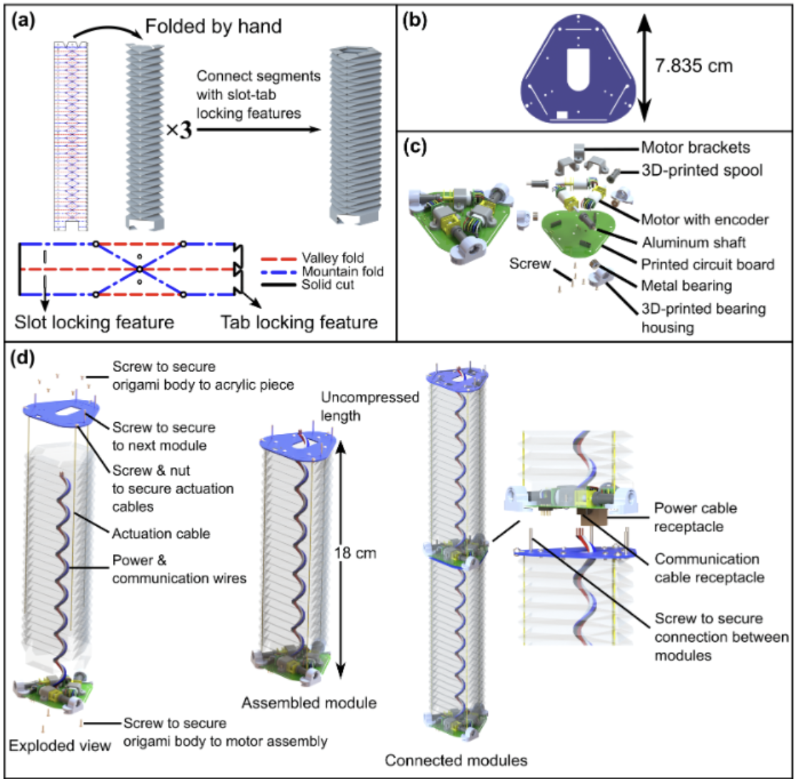
(a) Origami body assembly, (b) acrylic top plate, (c) motor assembly, (d) origami module assembly.1
Motion Planning
An optimization-based inverse kinematic solver was proposed to achieve smooth motions during a pick-and-place scenario.
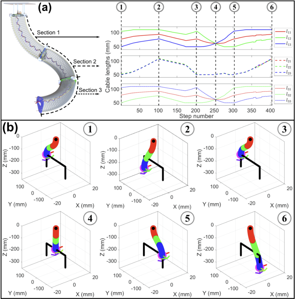
(a) Inverse kinematics solution for the three‐section continuum manipulator executing a pick‐and‐place motion. (b) Snapshot of the robot motion in simulation with the cost function that minimize motion between time steps.1
Demo of Robot Capabilities
Below are the screenshots showing some capabilities of the proposed continuum robot ranging from pick-and-place to robotic art.
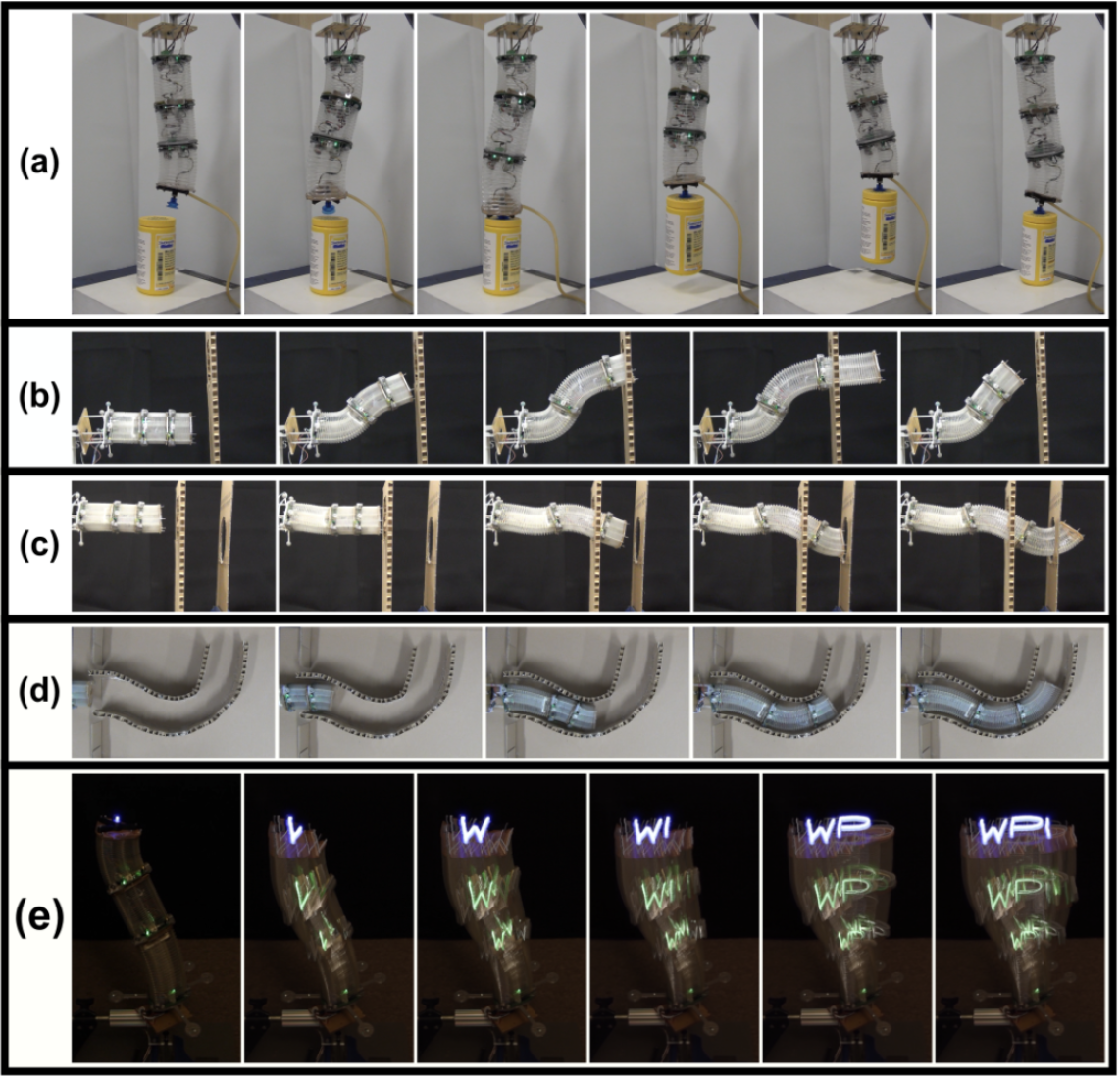
(a) pick‐and‐place, (b) traversing through a mockup wall with a single hole (side view), (c) traversing through walls with two holes (side view), (d) grow‐to‐shape routine with linear slider at the base (top view), (e) end‐effector path following to trace WPI letters. The direction of gravity is all pointing downward except for row d where the gravity direction is pointing into the page.1
For more details please refer to my dissertation.1