AlphaPasso: Perception
This section will discuss the perception system necessary to enable direct interaction between human and the robot.
Methodology
Game State Evaluation & Detection
ArUco marker for piece detection
For this project I am using the cv2 Python module to import ArUco marker detection functionality from OpenCV library. Markers detection is done via the detectMarkers function and marker poses are further obtained using the estimatePoseSingleMarkers function. I am using the 4x4_50 dictionary since there are only 35 playing pieces (tiles and disks) in total, so it can accommodate the smallest possible pieces. Each playing piece will be assigned an ArUco marker, ID 0-24 for the tiles, 25-29 for the black disks (AI player), 30-34 for the red disks (human player), and 35 is reserved for the move marker. The ArUco markers are represented in Gazebo sim using albedo_map, where PNG file of the ArUco markers are specified for the value (see Gazebo Sim documentation page here under Texture).
The ArUco marker detection functionality is encapsulated in a ROS 2 node (ArUco Node). The node subscribes to the raw image messages coming from the simulated RGB camera in Gazebo Sim and publishes the detected marker IDs and poses. The ros_gz_bridge package is used to enable the exchange of the image messages between ROS 2 and Gazebo Transport.
I am using 1280x720 resolution for the simulated camera, this value was chosen after experimenting with different preset values. The ArUco markers are able to be detected robustly with this camera resolution. Furthermore, I only specified the horizontal_fov value for the camera and using the default plumb bob distortion value calculated by Gazebo Sim. The horizontal_fov value was taken directly from the specification sheet of a camera that is compatible with the Robotis OMX arm. Camera calibration needs to be done when using the actual camera to obtain the intrinsic parameters. I did not end up needing the extrinsic camera parameters due to how the piece movement detection is done. Furthermore, there are options to choose between fixed-mount or end-effector mount for the camera location. I chose the former for its simplicity but there is no reason why the piece detection methods would not work with the latter setup as well. More details about these will be explained in the next section.
Piece movement detection
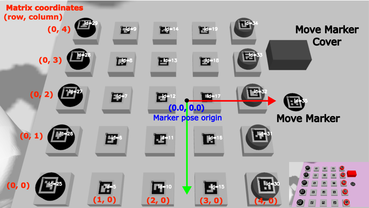
The piece movement detection functionality is contained in a separate ROS 2 node called PassoBoardStateEval Node. This node consumes the marker IDs and poses information generated by the ArUco Node. At the start of the node, the obtained marker IDs and poses information are utilized to construct the initial board state. First, the marker IDs are sorted based on its X and Y location. The sorting coupled with creating a dictionary (marker IDs->matrix coordinate) will enable the perception system to work with any arrangement of the playing pieces i.e. at the beginning of the game we do not need to arrange the pieces in a particular order. The picture below shows a nicely ordered marker IDs but one can start with any order. As long as we have 5x5 tiles and rows of red and black disks, the order of the tiles and disk pieces should not matter
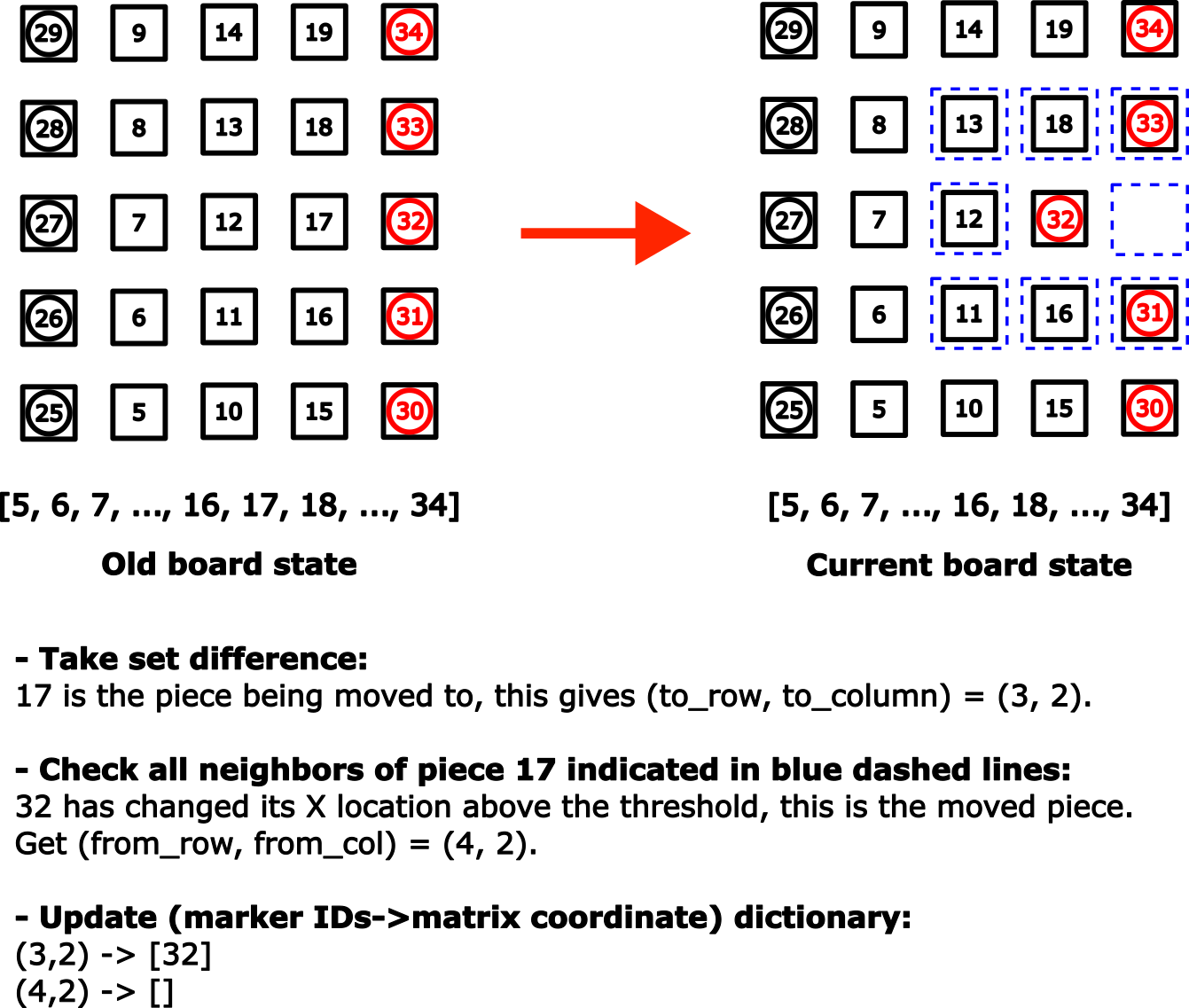
The Passo Node at which the game logic and AlphaPasso model reside in, expect human moves as input in the form of (from_row, from col, to_row, to_col). The algorithm to find these values is as follows. First, we need to determine which playing piece has just been covered. To do this, we only need to find the (set) difference between the new and old board states. This work since the disk pieces always cover the tile pieces (but not vice versa) and the fact that tile pieces are removed as soon as it no longer contains any disk pieces. Note that a disk piece can cover another disk piece. Once the newly covered piece is determined, then by using the (marker IDs->matrix coordinate) dictionary we can find the value of to_row and to_col. Next we will check the neighboring pieces of the covered piece. For each neighboring piece, we will check its newly reported X and Y location (obtained from marker pose). If either X or Y location of a certain piece has changed (compared with respect to the old board state) then this piece was the one being moved. Once again, we use the (marker IDs->matrix coordinate) dictionary to determine the value for from_row and from_col. It is important to update the dictionary with updated information once a move information is determined. See the figure below for illustration of the algorithm.
Since the ArUco Node constantly publishes the markers info with a certain rate, we need a way to trigger/signal the move detection process timely. I am using a move marker for this purpose. The move marker is basically an additional ArUco tag (with ID: 35) that will be covered every time we (human player) complete a move. When playing against the real robot, this method will also be effective to signal the robot that we (human) have completed our turn akin to chess players pressing the chess clock button. During simulation I am using the “done” signal from the MoveIt Task Constructor (MTC) as the “real” trigger. This is because it takes some amount of time for the robot to go back to the ready position after placing the move marker cover. This will prevent the move detection from happening during the robot motion, which may uintentionally obscuring the ArUco markers.
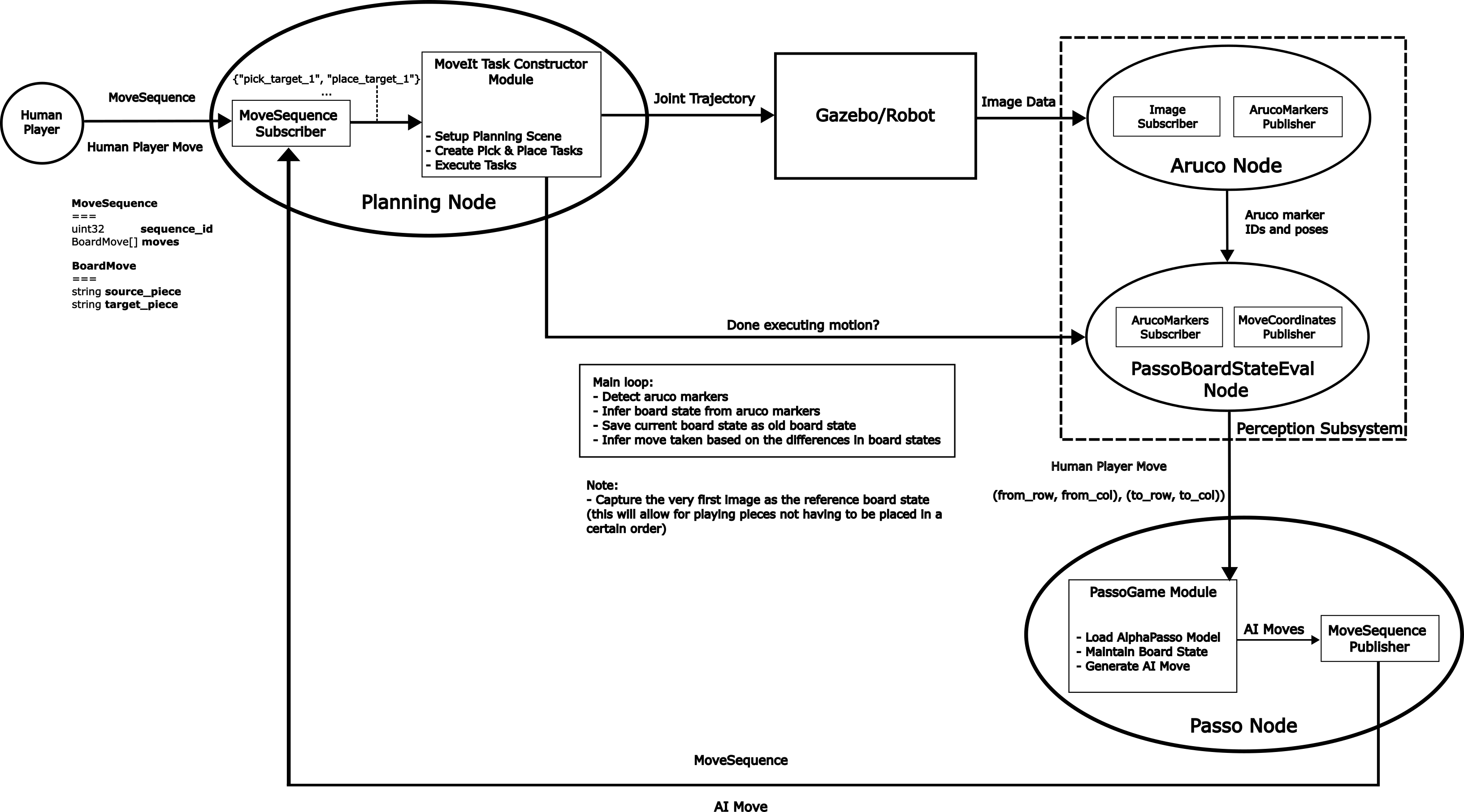
Here is the updated architecture diagram for the system with the added perception system.
Behavior Coordination and Execution
Initially, I thought a behavioral tree was absolutely necessary, but it proved unnecessary since the current system was mostly open-loop, with no recovery actions for failed pick-and-place tasks.
Below is the current logic flow:
While game is not over -> Evaluate board state until -> Human move is done (move marker covered) -> Moved piece detected -> AlphaPasso generate a move for AI player -> MoveIt Task Constructor start planning and executing motion -> Robot move is done (move marker uncovered) -> Record board state -> Loop back.
To emulate a human player move, a MoveSequence message is sent through ROS topic at which the simulated robot will use to plan and execute the desired motion. Refer to the previous project page here for more details on the MoveSequence message. In addition to pick-and-place actions involving the game pieces (tiles and disks), a motion to uncover the move marker (represented by ArUco tag ID 35) is added at the end of each human move sequence. Similarly, at the end of each AI player move, a motion to cover the move marker is inserted.
Result
GIF below shows a typical sequence between human and AI players. The GIF details each part previously described: human player move entry, robot motion planning and execution, and player move detection.
The terminal at the bottom right displays a MoveSequence message being published to command the robot to emulate a human turn in the game. The terminal on the bottom center shows the output of the perception system (node) that evaluates the board state and detects player moves. Lastly, the terminal on the bottom left shows the (AlphaPasso) game node, which is responsible for generating an AI move given a detected human move from the perception system as input.
A complete simulated game session can be seen in the GIF below (running at 50x speed), showcasing the end-to-end workflow with added functionality of the perception system to detect player moves. The simulated game session itself took about 35 minutes or so from the beginning to end, thus necesitates the 50x speed up for the GIF. The “slowness” mostly comes from the fact that Gazebo Sim is running slower than real time, at about 30% Real Time Factor (RTF). This is while using 100 Hz real_time_update_rate and 0.01 s max_time_step parameters in the sdf file. The robot motion completion time is in the order of minutes while the move detection and AI move generation time is in the order of seconds.
Future work
Here are some improvements I think will be beneficial:
- Utilize a behaviorial tree to enable more complicated behaviors. Currently the system is open loop, there is no recovery behavior for when the robot arm fails to pick the piece for example. Another useful behavior I could think of is suppose that human player made an invalid move then the robot can restore the board state to the previous state.
- Employ and enhance the perception subsystem to provide closed-loop feedback. Currently the perception subsystem is only used to detect piece movement, it is not being used for closed loop feedback. Suppose that the robot arm fails to pick a piece, then a recovery behavior would require a way to sense the current location of the piece. Determining the actual location of the piece would also require us to know the camera extrinsic parameters.
- Implement ROS Service and ROS Action for the perception and motion planning subsystems respectively. Currently, both subsystems are operating with ROS Topic. The perception (board state evaluation) subsystem subscribes to the ‘robot ready’ signal published by the motion planning (MTC) subsystem. The board state evaluation is triggered by this same signal. The ‘robot ready’ signal is published when all planned robot motions are completed succesfully. Since motion planning and execution are long-running tasks, thus using ROS Action would be appropriate. The feedback mechanism of pick-and-place status enabled by ROS Action will be useful when implementing a recovery behavior.
Barring the improvements above, the next steps to achieve a complete working system (including hardware) include:
- Porting and modifying the simulation setup to use the Robotis OMX arm robot description.
- Performing camera calibration to obtain the actual camera instrinsic parameters.
- Achieving reliable pick-and-place motions with the real robot.